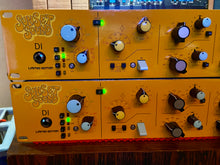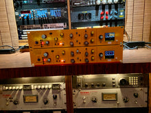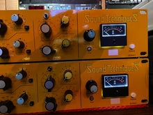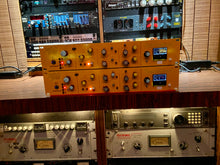
Sound Techniques Sunset Sound Limited Edition Channel Strip - ZR7064SS
When one of the best studios in the World makes a request, you listen! We are excited to release the Sound Techniques ZR7064 Sunset Sound Limited Edition in Sunset Orange. Only 32 units available. Each purchase will also include our soon to be released plug in package featuring Sunset Sound Chamber #1. More details to follow soon!
Activates phantom power for the mic input. It is a latching switch. Up is phantom off, down is phantom on with the LED lit
C/O
Changes over from Mic input to Line input and vice-versa. It is a latching switch; up is Mic with the red LED lit, down is Line with the green LED lit. Mic & Line inputs are on XLR connectors on the rear panel. The line input is also available on the DB25 connector.
DI
Selects the Direct Input (instrument input) on the front-panel jack socket. DI works in conjunction with the Mic input circuitry and facilities, however, it automatically sets parameters that provide the best electrical matching to the instrument signal characteristics. DI disables operation of the Z-Match switch, setting the circuitry to 200-Ohms at 0dB. Independently of the C/O switch, DI forces the Mic input to be active so as to allow the front panel jack socket to feed the mic input transformer and amplifier. A unique feature of the DI input is that it is balanced; generally instrument inputs are unbalanced.
Polarity
Swaps the signal polarity of the selected input.
SIG LED
This LED responds to the presence of a signal at the unit’s input. It illuminates when a level of -20dBu is present at the insert send.
Z-Match
Works as-per the ZR7064 channel, but with the noted exceptions for the DI input as detailed above.
Mic / Line Gain
Works as-per the ZR7064 channel.
PREQ
Switches the Pre-EQ insert return into the signal path. The insert send is always active. It is a transformer driven output.
EQ
The equalizer is as per the ZR7064 with LF bell response.
There are 5 control bands within the EQ:
LF: +/-15dB at 6 frequencies (30Hz to 270Hz). Gain is in 3dB steps. Five of the frequencies are bell response, with 80Hz being a specific shelving response frequency.
Low mid: 7 frequencies (200Hz to 1.6kHz) with +/-12dB at low Q and +/-18dB at high Q. Gain is continuously variable.
High mid: 7 frequencies (900Hz to 8kHz) with +/-12dB at low Q and +/-18dB at high Q. Gain is continuously variable.
HF Boost: 0dB to +18dB boost in 2dB steps. There are 9 frequencies available. Seven frequencies are peaking with Narrow, Mid and Wide bandwidth selection via a toggle switch (2kHz through to 12kHz). Two frequencies are shelving (7.5kHz and 15kHz).
HF Cut: 0dB to -14dB cut in (generally) 1.5dB steps. There are 8 frequencies available (2kHz to 15kHz) with a shelving response.
LF Filter: A 3-frequency LF filter is provided, the frequency selection being via two press-button switches. The slope is 18dB per octave. Frequencies are 40Hz, 80Hz and 120Hz.
The equalizer is switched into circuit by the lever switch. An associated LED lights when the EQ is active.
Master Level
A rotary pot with unity gain in the mid position. It has 10dB gain in hand.
Peak LED
The Peak LED drive circuit monitors three points within the unit:
Input stage (Mic / Line / DI),
Output of the equalizer,
Final output of the unit.
The LED illuminates when a level of +21dBu is detected at any of the monitor points.
Meter
The meter monitors the final output of the unit.
Power
Switches DC power to the unit.
External connections:
The functions of the 5 XLR connectors are as noted.
We have chosen to put the insert send and return on XLR connectors for reliability. It must be noted that operating the Insert PREQ switch without having an in-circuit external device or a loop cable across the send and return will result in signal loss.
The DB25 connectors allow for a pair of Mic Pre & EQ units to have their line level signals interfaced.
When interfacing using the DB25 connectors:
CONN1 is always used to provide connectivity to a patchbay or other form of external equipment.
For a single Mic Pre & EQ unit, CONN 1 signals are Line In, Insert Send, Insert Return and Unit Output. These signals are on DB25 circuits 1, 3, 5 and 7 respectively.
Ignore Conn 2.
Two Mic Pre & EQ units can be cascaded. Let us call them Unit 1 and Unit 2. Cascading allows us to make full use of the CONN 1 signals on Unit 1.
“Unit 2 Conn 1” links to “Unit 1 Conn 2” with a DB25 cable.
Internally, Conn 2 links to Conn 1.
In a linked system, for Unit 1, its Conn 1 becomes the connector that interfaces both units to an external patchbay. The result is that:
The signals of Unit 1 (line, send, return, out) are on Unit 1 Conn1 circuits 1, 3, 5, 7 respectively.
The signals from Unit 2 via the link cable (line, send, return, out) are on Unit 1 Conn1 circuits 2, 4, 6, 8 respectively.
External power
This is provided by a proprietary Sound Techniques universal adapter that can power up to 6 Mic Pre & EQ units by means of the power linking facility. Power supply is included with purchase


